Install Manual: Glide Away Front Sensor (IXIO)
Overview
IXI0-DT1
Opening and safety sensor for automatic sliding doors (according to EN 16005 and DIN 18650)
User's guide for product version 0100 and higher
IXI0-DT1
Opening and safety sensor for automatic sliding doors (according to EN 16005 and DIN 18650)
User's guide for product version 0100 and higher
-
1Parts and AccessoriesParts
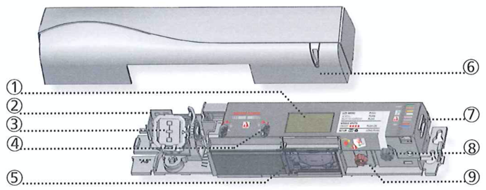
- LCD
- Radar antenna (narrow field)
- Radar Antenna (wide field)
- AIR-curtain width adjustment
- AIR-lenses
- Cover
- Main connector
- Main adjustment knob
- AIR-curtain angle adjustment knob
Accessories
BA: Bracket Accessory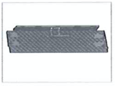 CA: Ceiling Accessory
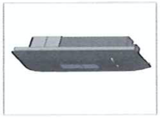 RA: Rain Accessory
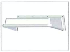
-
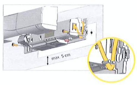
2Mounting and WiringTip: Fixation and wiring are compatible with the ACTIV8.
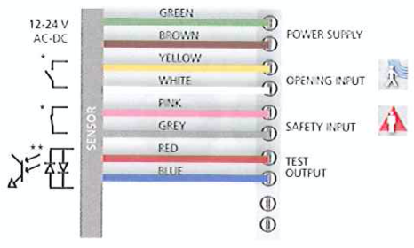 * Output status when sensor is operational
** For compliance with EN 16005 and DIN 18650, connection to door controller test output is required -
3Opening Impulse FieldAngle

Width
The size of the detection field varies according to the mounting height of the sensor. -
4Safety FieldAngle
 *Visibility depends on external conditions.
** The distance between the inner curtain of the inside door sensor and the inner curtain of the outside door sensor should always be smaller than 20 cm. The distance to the door leaf depends on the thickness of the door leaf.
Width
 The size of the detection field varies according to the mounting height of the sensor. The full door width must be covered.
-
5Settings
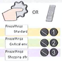 Adjust the sensor by LCD or remote control (see LCD and Settings Overview below) or choose one of the pre-settings.
- STANDARD: Inside installations
- CRITICAL ENVIRONMENT: Critical or outside installations
- SHOPPING STREET: Installations in narrow streets with pedestrian traffic
-
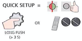
6SetupIMPORTANT!
- Step out of the detection field before launching a setup.
- Test and make sure the installation is functioning properly before leaving the premises.
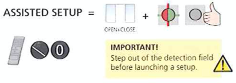
-
7LCD UsageDisplay During Normal Functioning
 Factory Value vs. Saved Value
Menu Navigation- Push to enter the LCD menu.

- Select your language before entering the first LCD menu.
Note: During the first 30 seconds after power-on of the sensor or later in the diagnostics menu.
- Scroll menu items.

- Select Back to return to the previous menu or display.

- Select More to go to the next level.

- Basic Settings
- Advanced Settings
- Diagnostics
Changing a Value- Scroll the menu up and down.
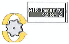
- Push to select a parameter.
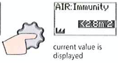
- Scroll values up and down.
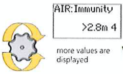
- Push to save the new value.
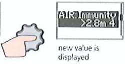
Value Check with Remote Control
Pressing a parameter symbol on your remote control displays the saved value directly on the LCD screen.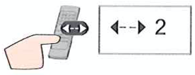
- Push to enter the LCD menu.
-
8Settings Overview
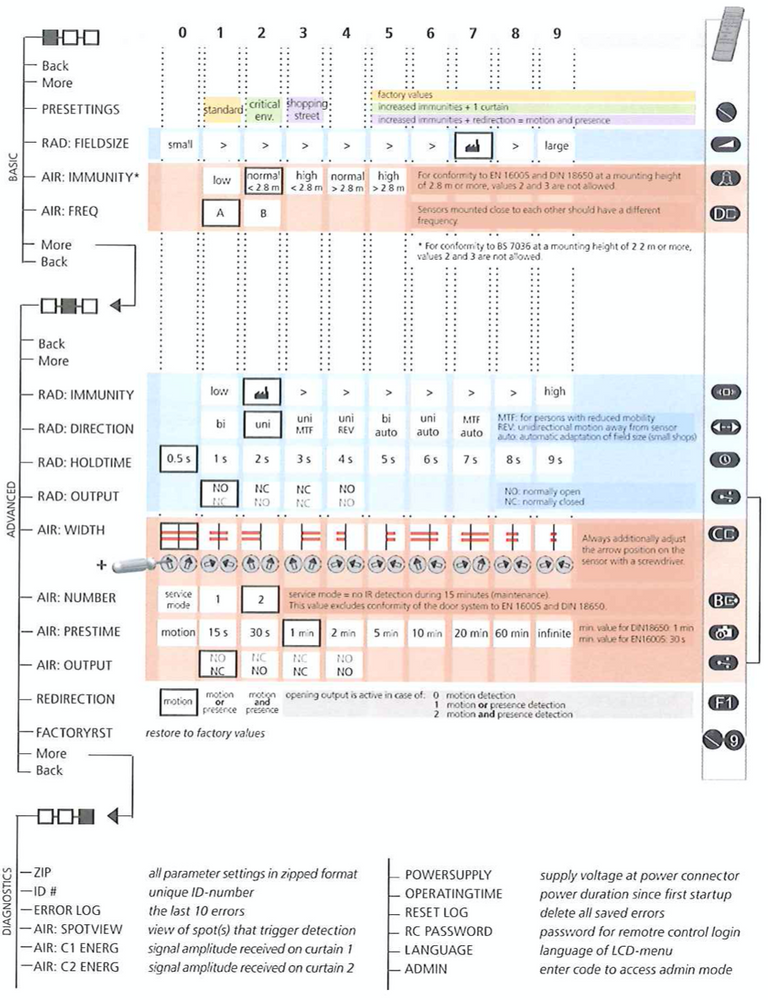
-
9Troubleshooting
E1 ORANGE LED flashes 1x 
The sensor signals an internal fault. - Cut and restore the power supply.
- If the ORANGE LED flashes again, replace the sensor.
E2 ORANGE LED flashes 2x 
The power supply is too low or too high. - Check the power supply (in the diagnostics menu of the LCD).
- Check wiring.
E4 ORANGE LED flashes 4x 
The sensor is not receiving enough AIR-energy. - Check the angle of the AIR-curtains.
- Increase AIR-immunity filter to value 4 or 5 (> 2.8 m).
E5 ORANGE LED flashes 5x 
The sensor is receiving too much AIR-energy. - Check the angle of the AIR-curtains.
- Increase AIR-immunity filter to value 1, 2, or 3.
E8 ORANGE LED flashes 8x 
The AIR power emitter is faulty. Replace the sensor. ORANGE LED is on 
The sensor is encountering a memory problem. - Cut and restore the power supply.
- If the Orange LED lights up again, replace the sensor.
RED LED flashes quickly after an assisted setup 
The sensor sees the door during the assisted setup. - Check the angle of the AIR-curtains.
- Launch a new assisted setup.
Attention: Do not stand in the detection field!
RED LED lights up sporadically 
The sensor is vibrating. - Check if the sensor is fastened firmly.
- Check the position of the cable and cover.
The sensor sees the door. - Launch an assisted setup and adjust the AIR angle.
The sensor is disturbed by external conditions. - Increase the AIR-immunity filter to value 3.
- Select presetting 2 or 3.
GREEN LED lights up sporadically 
The sensor is disturbed by rain and/or leaves. - Select presetting 2 or 3.
- Increase the radar-immunity filter.
Ghosting created by door movement. - Change the radar field angle.
The sensor is vibrating. - Check if the sensor and door cover are fastened firnly.
- Check the position of the cable and cover.
The sensor sees the door or other moving objects. - Remove the objects if possible.
- Change the radar field size or angle.
LED and LCD display are off 
- Cut and restore the power supply.
- Check wiring.
The reaction of the door does not correspond to the LED signal. - Check the output configuration setitng.
- Check wiring.
 Motion detection
 Presence detection
 LED flashes
 LED flashes quickly
 LED is off
 -
10InstallationAvoid extreme vibrations.
 Do not cover the sensor.
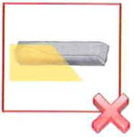 Avoid moving objects and light sources in the detection field.
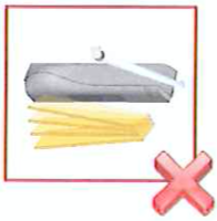 Avoid highly reflective objects in the infrared field.
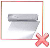
-
11MaintenanceIt is recommended to clean the optical parts at least once a year or more if required due to environmental conditions.
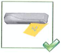
Do not use aggressive products to clean the optical parts.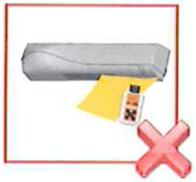
-
12SafetyThe door control unit and the door cover profile must be correctly earthed.
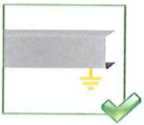
Only trained and qualified personnel may install and set up the sensor.
Always test and makes sure the installation is functioning properly before leaving the premises.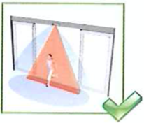
The warranty is invalid if unauthorized repairs are made or attempted by unauthorized personnel.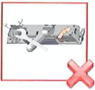
IMPORTANT!- The device cannot be used for purposes other than its intended use. All other uses cannot be guaranteed by the manufacturer of the sensor.
- The manufacturer of the door system is responsible for carrying out a risk assessment and installing the sensor and the door system in compliance with applicable national and international regulations and standards on door safety.
- The manufacturer of the sensor cannot be held responsible for incorrect installations or inappropriate adjustments of the sensor.
-
13Technical Specifications
Supply voltage 12V - 24V AC +/- 10%; 12V - 30V DC +/- 10% (to be operated from SELV compatible power supplies only) Power consumption < 2.5W Mounting height 2m to 3.5m (local regulations may have an impact on the acceptable mounting height) Temperature range -25C to +55C; 0-95% relative humidity, non condensing Degree of protection IP54 Expected lifetime 20 years Applicable directives R&TE 1999/5/EC; EMC 2004/108/EC; MD 2006/42/EC; RoHS 2002/95/EC Detection mode  Motion
Min. detection speed: 5 cm/s Presence
Typical response time: < 2000ms (max. 500ms)Technology Microwave doppler radar
Transmitter frequency: 24.150 GHz
Transmitter radiated power: < 20 dBm EIRP
Transmitter power density: < 5mW/sq.cmActive infrared with background analysis
Spot: 5cm x 5cm (typ)
Number of spots: max. 24 per curtain
Number of curtains: 2Output Solid-state-relay (potential and polarity free)
Max. contact current: 100 mA
Max. contact voltage: 42 V AC/DCSolid-state-relay (potential and polarity free)
Max contact current: 100 mA
Max contact voltage: 42V AC/DC
Holdtime: 0.3 to 1 sTest input Sensitivity: Low < 1V; High > 10V (max. 30V)
Response time on test request: typically < 5msNoise < 70 dB Norm conformity EN 12978
EN ISO 13849-1:2008 PL <<c>> CAT.2 (under the condition that the door control system monitors the sensor at least once per door cycle)
EN 16005:2012 Chapter 4.6.8; DIN 18650-1:2010 Chapter 5.7.4; BS 7036-1:1996 Chapter 8.1
Did this answer your question?
If you still have a question, we’re here to help. Contact us
